

Every technician knows the frustration of staring at an access port, knowing a critical component lies just beyond sight—around a bend, behind a baffle, or deep within a sealed assembly. Traditional rigid borescopes offered a limited glimpse into these hidden spaces, but their straight-line design meant that anything not directly in front of the lens remained invisible. Corners, curves, and complex internal geometries defeated them entirely. The articulating borescope has changed this reality. By giving operators full directional control over the camera tip, this tool transforms previously impossible inspections into routine procedures. Whether you’re examining engine cylinders in an automotive shop or surveying turbine blade erosion on the flight line, an articulating borescope delivers the visual access that accurate diagnostics demand. This article explores how articulating borescopes work, why they deliver superior results in tight space inspection, how to select the right model for your application, and a practical workflow that helps you get the most from every inspection session.
What is an Articulating Borescope? Defining the Modern Inspection Camera Probe
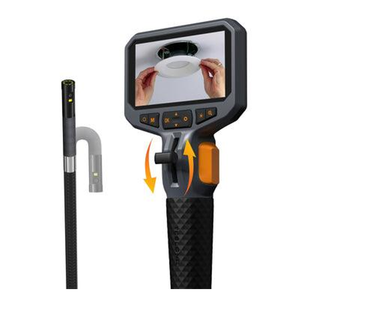
An articulating borescope is a flexible inspection instrument built around a camera-tipped probe that the operator can steer in multiple directions while it travels through confined passages. Unlike rigid borescopes, which only capture what lies directly ahead along a fixed axis, and semi-rigid models that bend passively against surfaces, an articulating borescope places active directional control in the technician’s hands. The defining component is the borescope articulating head—a precision-engineered tip section containing miniature pull wires connected to an external joystick or thumbwheel on the handset. When the operator deflects the control, these internal wires pull the tip through its range of motion, allowing it to look up, down, left, right, or anywhere in between with smooth, proportional response.
Integrated into that steerable tip are a high-resolution image sensor and multiple LED illumination sources that flood dark cavities with adjustable light. The live video feed transmits to a built-in display or connected monitor, giving the technician an immediate, detailed view of internal surfaces. This combination of maneuverability and imaging capability makes the tool indispensable across demanding industries. Automotive technicians thread articulating borescopes through spark plug ports to inspect cylinder walls and valve seats without pulling heads. Aviation maintenance crews navigate them through access panels to evaluate turbine blade leading edges, combustion chamber liners, and airframe structural members hidden behind insulation. In each scenario, the articulating borescope reaches areas that would otherwise require hours of disassembly to examine visually.


Key Benefits of an Articulating Borescope for Mechanical Inspection
Understanding what an articulating borescope does is one thing—recognizing how it transforms daily inspection workflows is what drives adoption among experienced technicians. The benefits extend far beyond simply “seeing more,” touching everything from diagnostic confidence to the bottom line of maintenance operations.
Unmatched Access and Improved Inspection Accuracy in Tight Spaces
The ability to steer the camera tip through bends, past baffles, and around structural obstructions means the technician achieves a complete visual survey of internal surfaces rather than a partial glimpse. In a turbine engine, for example, a rigid scope might reveal the leading edge of one blade, but an articulating borescope sweeps across the entire blade row, capturing erosion patterns, thermal coating loss, and foreign object damage that would otherwise go undetected until the next overhaul. This comprehensive coverage directly translates into improved diagnostic accuracy—technicians catch developing defects earlier, make informed go/no-go decisions with greater confidence, and ultimately prevent in-service failures that compromise safety. When every surface within a cavity can be examined on demand, the inspection becomes a reliable data source rather than a best-guess exercise.
Reducing Maintenance Costs Through Efficient Diagnostics
Exploratory disassembly is one of the most expensive activities in any maintenance program. Every removed panel, lifted cylinder head, or separated flange consumes labor hours, introduces the risk of installation errors, and requires fresh gaskets or hardware. An articulating borescope eliminates much of this exploratory work by providing definitive visual evidence of a component’s condition through existing access ports. Technicians pinpoint the exact location and severity of a fault, order only the parts actually needed, and proceed directly to a targeted repair. Beyond reactive fixes, the tool supports condition-based preventative maintenance—regular borescope surveys track defect progression over time, allowing shops to schedule interventions before minor wear escalates into catastrophic and costly failures.
Enhanced Documentation and Reporting
Modern articulating borescopes capture high-resolution photos and video during the inspection, creating a permanent visual record tied to specific assets and service dates. Many units include onboard measurement tools—comparative scaling, shadow measurement, or stereo measurement—that let technicians quantify crack length, pit depth, or coating loss directly on the live image. These documented findings feed into maintenance reports, satisfy regulatory audit requirements in aviation, and give clients transparent evidence supporting repair recommendations. Over successive inspections, stored imagery reveals how a defect evolves, enabling data-driven decisions about repair timing and extending component service life where conditions permit.

How to Choose the Right Articulating Borescope for Your Needs
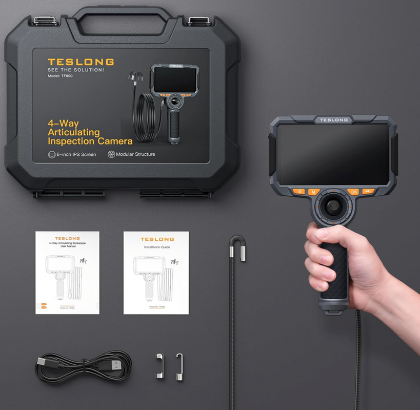
Selecting an articulating borescope requires matching the tool’s capabilities to the specific inspection challenges you face daily. A scope that excels in automotive cylinder inspection may fall short when navigating the complex internal passages of an aircraft gas turbine. Manufacturers like Teslong offer a range of articulating models designed for different probe diameters and working lengths, making it easier to find a unit tailored to your application. By evaluating a few critical specifications against your operational requirements, you can invest in a unit that delivers reliable performance across your most demanding tasks.
Articulation Range and Directional Control
The articulation system determines how effectively you can navigate complex geometries and position the camera for a clear view. Four-way articulation—providing independent up, down, left, and right tip deflection—is the baseline for professional use, while full 360-degree continuous rotation offers maximum flexibility in cavities where the target surface could be in any orientation relative to the insertion path. Beyond raw range, pay close attention to control responsiveness. A joystick that delivers smooth, proportional tip movement allows precise positioning on a small defect, whereas a stiff or notchy control makes fine adjustments frustrating and time-consuming. If your work involves threading through multiple tight bends before reaching the inspection area, look for a tip that achieves at least 150 degrees of deflection in each direction so you can make sharp turns without withdrawing and re-inserting the probe.
Camera Probe Specifications: Diameter, Length, and Resolution
Probe diameter dictates which access points you can use. Automotive spark plug ports and small borescope bosses on turbine casings often require probes in the 4 mm to 6 mm range, while larger industrial equipment may accommodate 8 mm or greater. Always verify that the probe clears your smallest access point with enough margin to articulate freely inside the cavity. Working length must reach the farthest inspection target from the insertion point—automotive applications may need only 1 to 1.5 meters, whereas aircraft engine inspections can demand 3 meters or more. Image resolution is equally critical; a sensor capable of resolving hairline cracks, early pitting, or subtle coating delamination prevents you from missing defects that a lower-resolution camera would blur into the background texture of the material.
Durability and Environmental Considerations
Inspection environments are rarely clean or gentle. In automotive shops, the probe encounters residual engine oil, coolant, and carbon deposits. Aviation maintenance exposes equipment to hydraulic fluid, jet fuel residue, and fine metallic dust. Choose a borescope with an IP-rated probe tip—IP67 or higher ensures the camera and articulation mechanism survive immersion in fluids encountered during wet inspections. The insertion tube itself should resist chemical degradation from petroleum products and solvents common in both industries. Beyond fluid resistance, consider the overall build quality of the handset and cable. A ruggedized housing with shock-absorbing features protects the instrument when it inevitably gets set down on a tool cart or bumped against engine hardware. Investing in a durable unit avoids costly repairs and downtime that undermine the efficiency gains the borescope is supposed to deliver.
A Step-by-Step Guide to Effective Tight Space Inspection
Owning a capable articulating borescope is only half the equation—applying a disciplined inspection workflow determines whether you extract maximum diagnostic value from every session. The following four-step process helps technicians conduct thorough, repeatable inspections that yield actionable findings rather than ambiguous images.
Step 1: Pre-Inspection Planning and Access Point Identification
Before the probe leaves its case, consult the equipment’s technical manual, cross-sectional diagrams, or maintenance planning documents to understand the internal geometry you’re about to navigate. Identify all available access points—borescope ports, spark plug holes, drain plugs, or inspection panels—and select the one that provides the most direct path to your target area with the fewest bends. Consider the probe’s working length and articulation range against the distance and turns required. If multiple access points exist, choose the route that keeps the insertion tube as straight as possible for the longest distance, reserving articulation capability for final positioning at the inspection zone. Note any known obstructions such as baffles, wiring harnesses, or fluid residue that could interfere with navigation, and prepare cleaning supplies or guide tubes accordingly.
Step 2: Safe Insertion and Navigating the Camera Probe
Insert the probe with the articulation in its neutral, straight position to minimize the tip’s profile as it enters the access point. Advance slowly, watching the live feed continuously to monitor the path ahead. When you encounter a bend or obstruction, use the joystick to deflect the tip gently in the required direction—never force the insertion tube around a corner by pushing harder. Let the articulation do the steering work while your push hand provides only forward travel. If resistance builds unexpectedly, stop, pull back slightly, re-orient the tip, and try again. This technique protects both the probe’s internal wires and the component’s delicate internal surfaces from scoring or damage.
Step 3: Systematic Visual Scanning and Defect Identification
Once the camera reaches the inspection zone, adopt a methodical scanning pattern rather than sweeping randomly. In cylindrical cavities like engine cylinders or pipe interiors, use a clock-position approach—start at twelve o’clock and slowly pan the tip through each position around the circumference before advancing to the next axial section. For flat or irregular surfaces, work top-to-bottom in overlapping passes. Adjust LED brightness to avoid glare on reflective metals while maintaining enough illumination to reveal subtle surface irregularities. Train your eye to recognize common defect signatures on screen: hairline cracks appear as fine dark lines that persist across lighting angles, corrosion presents as discolored pitting or raised deposits, wear shows as polished or thinned surfaces deviating from surrounding texture, and foreign object debris appears as loose material resting on or embedded in components.
Step 4: Documentation and Post-Inspection Analysis
When you identify a defect or area of concern, freeze the image or switch to photo capture mode and record a clear, well-lit still that shows the defect in context with surrounding features. Capture a short video clip panning across the area to provide spatial reference for anyone reviewing the findings later. If your borescope includes onboard measurement tools, apply them immediately while the probe is still positioned—measure crack length, pit diameter, or material loss depth and save the annotated image. After withdrawing the probe, transfer all captured media into the asset’s maintenance record, linking each image to the specific component location using the nomenclature from your planning documents. Compare current findings against previous inspection imagery to assess defect progression rates, and use this trend data to inform your repair recommendation or schedule the next inspection interval with confidence.
See also: How Wearable Tech Is Enhancing Player Performance in Golf
Why Articulating Borescopes Are Essential for Modern Maintenance
The articulating borescope has earned its place as an essential instrument in the modern technician’s toolkit by solving a problem that once consumed hours of labor and introduced unnecessary risk: gaining clear visual access to confined, complex internal spaces. Where rigid scopes could only peer straight ahead and disassembly was the default alternative, articulating technology now delivers complete cavity coverage through existing access points, turning guesswork into confirmed diagnosis. The benefits compound across every maintenance operation—improved inspection accuracy catches developing faults before they escalate, targeted repairs replace costly exploratory teardowns, and documented visual evidence strengthens reporting and regulatory compliance. While the initial investment in a quality articulating borescope represents a meaningful commitment, the return arrives quickly through reduced labor hours, fewer unnecessary part replacements, and extended component service life driven by condition-based maintenance decisions. As imaging sensors grow sharper, probe diameters shrink further, and digital integration connects inspection data directly to maintenance management systems, the articulating borescope will continue expanding what skilled technicians can diagnose, document, and resolve—without ever lifting a wrench to disassemble what they can already see.