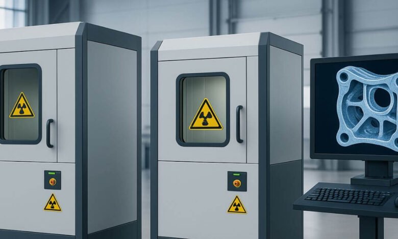
X-ray inspection helps engineers examine internal structures without damaging an object. Image usefulness depends not only on detector quality or exposure settings, but also on the area where electrons strike the X-ray tube target. This area, called the focal spot, influences how sharply small features appear. A microfocus X-ray source can support detailed imaging when its focal spot, geometry, and operating conditions suit the inspection task. Understanding this relationship helps equipment developers make informed choices about image quality and system design.
Understanding Focal Spot Size and Image Formation
The focal spot is the region on the anode target where electrons produce X-rays. Its dimensions affect how the source projects an object’s internal features onto a detector. A larger focal spot can create more geometric blur, while a smaller one can preserve finer boundaries under suitable conditions.
Image detail is also influenced by magnification, detector pixel size, object position, and source-to-object distance. Therefore, focal spot size should not be considered in isolation. Engineers need to evaluate the complete imaging geometry and inspection goal to determine whether a smaller spot will meaningfully improve the final image.




Why Smaller Focal Spots Can Reveal More Detail
Geometric unsharpness occurs because X-rays originate from an area rather than a perfect point. Rays from different parts of that area project slightly different outlines onto the detector. When the focal spot is reduced, this spread can become smaller, helping edges and closely spaced features appear more distinct.
A microfocus X-ray source is useful when inspection requires examination of fine internal structures, such as small solder connections, thin material features, or compact assemblies. Yet a smaller focal spot does not automatically guarantee a sharper image. Detector resolution, vibration, motion, contrast, and exposure conditions can limit the detail ultimately recorded.
1. Reducing Geometric Unsharpness
A smaller focal spot can reduce the width of blurred edges created by projection geometry. This is valuable when inspecting components with narrow gaps, fine boundaries, or closely positioned structures. The benefit depends on maintaining suitable distances and stable positioning throughout exposure.
2. Supporting Useful Magnification
Magnification enlarges an object’s projected image, allowing small features to occupy more detector pixels. However, increased magnification can also amplify geometric blur. A smaller focal spot helps manage this trade-off, enabling engineers to select useful magnification without sacrificing too much edge definition.
3. Improving Separation Between Nearby Features
When two structures sit close together, blur may cause their projected boundaries to overlap. Reducing focal spot size can help preserve their distinction, provided detector resolution and contrast are adequate. This can support more confident interpretation of complex internal arrangements.
4. Revealing Fine Material Boundaries
Small focal spots can make subtle edges more visible in components with intricate shapes or layered construction. The improvement is most useful when material contrast provides enough information for the detector to distinguish the feature. Image processing cannot fully recover detail lost during image formation.
5. Supporting Repeatable Inspection Comparisons
Consistent source geometry helps maintain comparable image characteristics across repeated examinations. When focal spot behaviour remains within specified operating conditions, inspection teams can compare images more reliably. Repeatability still depends on stable positioning, controlled exposure, detector performance, and consistent procedures.
Balancing Focal Spot Size With Operating Conditions
A smaller focal spot often requires careful management of tube power and heat. Concentrating electron energy into a smaller target area can increase thermal loading, so the tube may need to operate within specific power limits. Engineers should review rated voltage, current, focal spot specifications, and duty cycle before choosing settings for detailed inspection.
The right configuration balances detail with practical performance. Higher magnification, longer exposure, or increased output may improve some image characteristics, but each choice can affect inspection speed, heat, motion sensitivity, or component life. The best setup meets inspection criteria while remaining within the equipment’s documented limits.
Applications Where Focal Spot Detail Matters
Focal spot selection becomes important when inspection targets contain small or closely spaced internal features. Different industries have distinct requirements, so engineers should match source characteristics to the object, material, and expected findings rather than applying one configuration universally.
Common applications include:
- Electronics Inspection: Reviewing solder joints, connections, and internal component structures.
- Industrial Nondestructive Testing: Examining small features, joints, and material discontinuities.
- Precision Component Analysis: Inspecting compact assemblies with overlapping internal elements.
- Research and Analytical Systems: Capturing detailed projections of small samples.
- Quality Assurance: Comparing internal features against defined inspection criteria.
These applications may require different combinations of focal spot size, magnification, detector resolution, and exposure. A clear inspection objective helps determine which factors deserve priority.
Practical Factors to Evaluate Before Choosing a Source
Before selecting an X-ray source for detailed inspection, engineers should review:
- Required feature size and image detail
- Focal spot specification at intended operating conditions
- Tube voltage, current, and power limits
- Magnification and source-to-object geometry
- Detector pixel size and sensitivity
- Object material, thickness, and contrast
- Exposure time, motion, and expected throughput
- Thermal management and duty-cycle requirements
- Mounting stability and system integration needs
These checks help prevent source selection without considering the entire imaging chain. Testing with representative samples can confirm whether the planned configuration delivers the required information.
Conclusion
Focal spot size influences the sharpness of projected edges and the visibility of small internal features in X-ray inspection. Smaller spots can reduce geometric unsharpness and support useful magnification, but results also depend on detector performance, geometry, contrast, power, and thermal limits. Careful system-level evaluation helps developers choose a configuration that meets the inspection objective.
If you are looking for source technology and power components for precision inspection equipment, VJ X-Ray offers integrated X-ray sources and high-voltage generators for OEM applications. Its engineering expertise and customizable options can help developers assess suitable configurations for their systems. For teams comparing high-voltage power supply manufacturers, VJ X-Ray provides a technical partner focused on source integration, reliable design, and application requirements.