Most inspection cameras help you answer a simple question: What does it look like inside? A measuring inspection camera goes a step further by helping you answer: How big is it? That difference matters whenever you’re evaluating damage, wear, corrosion, cracks, or erosion in places that are hard to reach and even harder to measure with traditional tools.
Measuring inspection cameras are used in maintenance and quality environments where decisions depend on dimensions – not just appearance. Instead of relying on whether it seems small or appears worse than last time, inspectors can capture a visual record and attach measurements to it. Companies such as USA Borescopes help teams source inspection equipment that supports both remote viewing and measurement-driven decision-making.
Measuring Inspection Camera vs. Standard Borescope
A standard borescope (or non-measuring inspection camera) is primarily a visual confirmation tool. It’s extremely useful for detecting problems inside engines, equipment housings, pipes, and other confined spaces – especially when disassembly is costly or time-consuming.
A measuring inspection camera adds a measurement layer that can support decisions such as:
- Is that crack within an acceptable size range?
- How deep is the pit compared to a serviceability threshold?
- What’s the approximate area of erosion or coating loss?
- Has a defect grown since the last inspection?
In short:
- Standard camera: We can see a defect.
- Measuring camera: We can see it and document its size.
That shift often reduces ambiguity, improves communication between teams, and helps with trending over time.
See also: Tech Innovations and Business Growth 3357694990
How Do These Cameras Measure? (High-Level)
Measuring inspection cameras don’t touch the defect like a caliper would. Instead, they use optics + calibration + software to estimate dimensions based on how the target appears in the image (and sometimes how it appears from multiple angles).
While the implementation varies by manufacturer, the general idea is that the system uses known parameters – like lens characteristics, camera geometry, and sometimes patterns of light or multiple viewpoints – to interpret depth and distance.
Common measurement approaches you’ll hear described include:
Stereo / 3D Reconstruction Concepts
Some systems infer depth by comparing how a feature appears from slightly different perspectives, then reconstructing a surface model. The software uses that model to calculate distances, depths, and areas.
Structured-Light Style Concepts
Some measuring systems project a known pattern or use controlled lighting behavior to help the software interpret surface shape. This is often discussed in the broader context of 3D scanning and depth mapping – though the exact technique depends on the device.
Software-Assisted Geometry Based on Calibration
Even without obvious projected patterns, measuring cameras rely on calibrated optics and algorithms to translate pixels into approximate real-world dimensions under defined conditions.
A practical way to think about it: measurement works best when the camera can understand the scene geometry clearly – meaning you have good focus, stable positioning, and a view that isn’t compromised by glare or debris.
What Impacts Accuracy Most
Even with a good device, measurement quality depends heavily on how the image is captured. Key factors include:
- Distance to target: Too close or too far can reduce reliability.
- Angle: Measurements can degrade if the surface isn’t viewed in a stable, appropriate orientation.
- Stability: Tip drift or movement during capture can affect results.
- Surface reflectivity: Highly reflective metals can create glare and wash out edges.
- Lens condition: Oil haze, soot, and contamination soften edges and reduce clarity.
Because technique is so influential, organizations often get the best results when measurement capture is standardized – same approach, similar angles, and repeatable documentation steps.
Common Measurement Tasks

Measuring inspection cameras are typically used for tasks where size directly affects the decision. Common measurement categories include:
Length and Distance Measurements
- Crack length or propagation
- Distance between features (gap, spacing, edge breaks)
- Length of a nick or gouge
Depth or Step Measurements
- Pit depth from corrosion
- Depth of localized wear
- Step height differences between surfaces
Area Measurements
- Approximate area of erosion or coating loss
- Affected surface area in a region of interest
Trending Over Time
Even when a single measurement is borderline, measurement becomes especially valuable across time:
- Capture a reference view and baseline measurement.
- Repeat the inspection at intervals.
- Compare results to determine whether the defect is stable or progressing.
That trend data can improve planning decisions – repair now, monitor, or schedule work during a planned maintenance window.
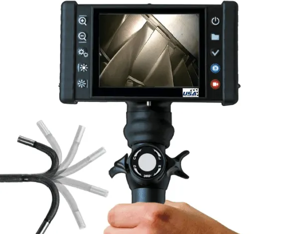
Core Components to Know
Measuring inspection cameras combine hardware and software. Understanding the main components helps you evaluate what you’re actually buying.
Probe (Diameter, Length, and Durability)
- Diameter: Determines access through ports and tight pathways.
- Length: Determines reach; longer isn’t always better if controllability suffers.
- Environment tolerance: Consider oil, temperature, abrasion, and handling.
Articulation and Navigation
- Two-way or four-way articulation
- Tip stability, stiffness, and control ergonomics
- Tip locking/holding features can help stabilize measurement capture
Camera Head, Optics, and Lighting
- Resolution and clarity affect measurement confidence.
- Lighting control matters for glare management and edge visibility.
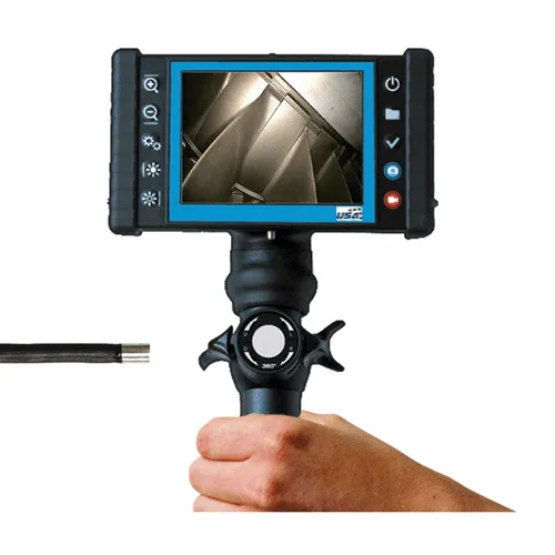
Monitor / Display and Control Unit
- Usability matters: if controls are awkward, inspections slow down and measurement consistency drops.
Measurement and Reporting Software
- Measurement modes (length, depth, area, etc.)
- Annotations and overlays
- Report exports and file management tools
If your workflow requires reporting for QA or engineering review, software usability may be as important as the probe.
A Practical Workflow (From Setup to Report)
A measuring inspection camera provides the most value when it’s part of a consistent inspection process. A practical workflow often looks like this:
- Prepare access and cleaning
- Ensure access ports are safe and appropriate.
- Clean the lens and confirm lighting and focus.
- Navigate to the target
- Capture a contextual image (where is this defect located?).
- Stabilize the tip before measurement.
- Capture measurement-ready views
- Adjust angle and distance for clarity.
- Reduce glare; confirm edges are visible.
- Measure and annotate
- Use the appropriate measurement mode.
- Add notes that matter later: location, orientation, stage, component reference.
- Export and store
- Generate a report or export images with overlays.
- Save files with consistent naming for easy trending and future comparison.
When this process is consistent, measuring cameras can reduce re-inspections, shorten review cycles, and improve the quality of decisions.
Limitations and Best Practices
Measuring inspection cameras are powerful, but they aren’t magic. Understanding limitations helps avoid disappointment and misuse.
Common limitations
- Highly reflective surfaces can cause glare that hides edges.
- Deep cavities can limit lighting and focus.
- Curved or irregular geometry can make measurements more sensitive to angle.
- Dirty environments (oil, soot, debris) reduce image clarity and measurement confidence.
Best practices
- Treat measurements as decision-support data and follow relevant procedures.
- Capture multiple angles when surfaces are curved or hard to interpret.
- Standardize technique across technicians to improve repeatability.
- Use consistent reference views for trending over time.
Measurement is most valuable when it’s repeatable. The goal isn’t just a number – it’s a number you can trust and compare later.
What to Look For When Buying One
When evaluating a measuring inspection camera, focus on fit and workflow:
- Access fit: diameter, length, articulation suited to your targets
- Measurement capability: modes you actually need (length/depth/area)
- Image quality: clarity in your real environment, not just a clean demo
- Reporting tools: easy exports, overlays, and record storage
- Support: service, repairs, accessories, and training availability
A device that looks great on paper can fail operationally if it can’t reach your targets reliably or if the software is too painful for consistent reporting.
A Measuring Inspection Camera Makes Findings Actionable
A measuring inspection camera bridges the gap between seeing something and knowing what it means. By pairing remote visual inspection with measurement tools, it helps teams document defect size, reduce uncertainty, and support consistent decisions – especially when disassembly would be expensive or disruptive.
For teams exploring options, USA Borescopes offers inspection solutions and a wide range of equipment and accessories on the products page. If you want help matching a system to your application, measurement needs, and access constraints, you can contact USA Borescopes to discuss the best fit.
About the Author
The author is an independent inspection and maintenance specialist with extensive experience implementing remote visual inspection programs across industrial and transportation sectors. They focus on practical measurement technique, tool evaluation, and documentation workflows that reduce repeat inspections and improve decision quality. The author is not affiliated with any manufacturer or distributor and provides objective guidance.