
In circuit level power control, impedance is the amount of inductance across the input and output lines. The impedance is expressed in ohms, and modern PCBs do not suffer from parasitic losses. However, basic circuit simulators can still provide a definite value for the impedance, as they compensate for inductive and capacitive components. A circuit simulator may also contain an aggregate starter that houses the circuit breakers and motor starter visit this website lyntec.com
Impedance of the driver
In circuit level power control, the driver output impedance plays an important role in circuit-level power control. In fact, it is the single most important factor affecting the performance of power drivers. As the gate-to-source voltage of a driver approaches 0 V, the diode helps less. As a result, the driver output impedance must be less than the drive signal’s value.
Resonant circuit
To calculate resonant power, a circuit must have at least one resonant point. The resonant frequency is the frequency of the circuit, and its bandwidth is the range of frequencies over which half of its maximum power is provided. The sharpness of the resonant point is measured by a quantity known as the Quality factor, Q. It measures the peak energy stored in the circuit versus the energy dissipated by the system. A higher quality factor means a smaller bandwidth.


DC current in the transformer
In order to change the AC voltage from one side of a transformer to another, the device uses two coils of wire. A one-to-one transformer changes the AC voltage on both sides, but the secondary has a lower voltage. Moreover, the transformer is used for DC isolation. It can be used both forwards and backwards. Here are some common transformer uses. Let’s learn how they work. Describe the Transformer Action usglobalworld.
Outphasing PA with DPC
DPC is a circuit level power control (CLPC) technique that reduces the output noise power by minimizing non-idealities. Outphasing circuit level power control (DPC) software reduces these non-idealities by minimizing output phase offset and S1-S2 phase mismatch. Outphasing power ranges for high-power modes exceed 38 dB, while low-power modes only reach 12% PAE.
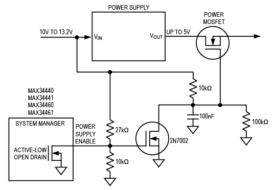
Bootstrap components
This circuit illustrates a circuit level power control system using a bootstrap capacitor. The bootstrap capacitor acts as a voltage source and is connected to the VDD power supply. It is recharged by the larger bypass capacitor, typically the VDD bypass capacitor. The bypass capacitor should be at least ten times larger than the bootstrap capacitor. This ratio ensures that the bootstrap capacitor does not drain during charging while the VDD capacitor is recharged. Similarly, the 10x bypass capacitor ratio is suitable for worst-case ripple of the VDD capacitor.
PWM controller
In electronic design, Circuit Level Power Control (CLPC) is an essential component of high-side and low-side driver ICs. Initially, CLP has been used for body functions, and later for LED lighting. LEDs are a common feature of automobile headlights, and these systems typically contain a single high-side smart LED driver IC. Moreover, circuit level power control is also used to design and implement a variety of other electrical components, including switches and relays.
Schottky diode
In N+1 configurations, schottky diodes are used to increase the system’s redundancy and power capacity. In this configuration, a minimum ‘N’ of power supplies is required to supply the load. The additional supply unit provides redundancy in case one of the units fails. The higher voltage supply delivers the most power to the load, and the lower voltage provides redundancy in case one of the units fails. The DC set point of the higher-voltage supply is adjusted to match the other units closely.
Inductor
An inductor is a passive electrical component consisting of a wire coil wound around a central core. When current flows through the coil, it induces a magnetic field around it. It also has the additional name of choke. Inductors generate a magnetic field when current flows through them. As the current flows through the coil, the magnetic field increases in strength. When the current decreases, the magnetic field collapses.